| Drawing Size and Scale
|
The
Drawing Size is the paper size of the
printed drawing. PlantDrafter has been programmed with the standard sizes of A,
B, C, D, and E in inch based projects and A0, A1, A2, A3, and A4 in metric
projects. You can select only the sizes that match the project units.
Note: Bentley
Systems only provides sheet files for E and A0 paper sizes. Sheet files for all
other drawing sizes need to use the naming format
<size>sheet.sht.
There are two scale attributes for a drawing:
Paper Scale and
CAD Scale. The Paper Scale is used to set
the reduction of the drawing contents to fit the Drawing Size. The default
value for the Paper Scale is
<auto> meaning that
PlantDrafter automatically calculates the necessary
scale to fit the page. If you are not satisfied with the scale used by
PlantDrafter, you are free to select from the standard scales in the drop down
list. When a drawing is opened, the dialog displays the scale being used. When
a drawing is closed, the dialog will show what scale was last used.
There are two options for CAD Scale:
Paper and
Full. When set to Paper,
PlantDrafter sizes all of the drawing’s contents to
fit the Drawing Size selected. Full scale, however, sizes the symbols to match
the actual 3D size of the model.
|
| Pipelines
|
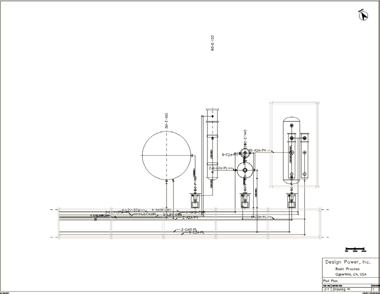
Rather than having a separate type for transposition
drawings, you select if the drawing should include the pipelines or not.
Setting the
Show Pipelines to
Yes, the drawing includes annotated
centerlines. The model must be routed for pipeline data to be included in a
drawing.
As shown above, even simple transposition drawings
contain a larger amount of data than plain plan drawings and need more user
attention to detail.
Along with pipelines, transposition drawings include annotated
named inlines such as the flow element.
Additional routing detail included in transposition
drawings include tees and vertical drops such as those shown below.
It is important to note that when Show Pipelines is turned on,
equipment pull spaces are not drawn.
- Pipeline
Tags - The
Pipeline Tags section of the
PlantDrafter Template Editor allows you to specify how pipelines are labelled
in a PlantDrafter drawing.

PlantDrafter Template Editor
show-ing the Pipeline Tags tab.
The formation of the label associated with each
pipeline is generated by dragging the pipeline attributes between the
Pipeline Parameters column to the
Display Tag Sequence column. Once the
desired attributes are in the sequence column, they can be ordered by dragging
and dropping the attributes into the necessary location. In the drawing, each
attribute are separated by a dash ( – ).
|
| Labels
|
There are three attributes for equipment labels:
Labels at Edges,
Show All Labels, and
Text Height.
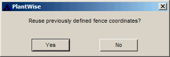
PlantDrafter plan drawing with
Labels at Edges set to Yes.
- Labels at
Edges pulls equipment tags towards the outer edges of the page with
dashed lines to indicate the location of the equipment’s placement point. While
there
PlantDrafter has some intelligence
about how far to pull the labels, which direction to pull the labels, and
placement of labels that could overlap, you are encouraged to examine the final
drawing output for clarity.
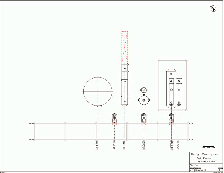
- Detached drawings
are designed to show layout detail within structures. However,
PlantDrafter places labels and pull
space graphics on equipment instances within a structure if the attribute
Show All Labels is turned on.
Duplicate layout of equipment
within a structure with Show All Labels set to No on the left and Yes on the
right.
The left side of above figure shows how the labels and
pull spaces are not included for elevated equipment inside a structure in a
standard plan drawing. On the right, is the same structure/equipment layout
with the Show All Labels property turned on.
- You set the height
of equipment tags from the
Text Height field. That value will also
be used for the text of detached view labels, inline component labels, and
pipeline tags that are not associated with leaders. The text size of tags that
are labeled with leaders is set via CAD, see " Leader Text Dimensions" in
Design File Settings.
for instructions on setting text size on leaders.
|
| Cell Library
|
To include standard symbols in a
PlantDrafter drawing, you need to specify
the cell library that contains the desired symbols. A drawing template can
reference only one cell library; therefore, you are encouraged to consolidate
their symbols into a single cell library per unit system.
|
| Views
|
There are four view types you can select from:
—plan, detached plan, fenced plan, and isometric.
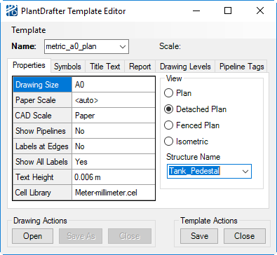
PlantDrafter Template Editor
showing a Detached Plan view selection.
- Plan - A
Plan drawing is a top view picture of
all the contents of the model (with the possible exception of pipelines) at the
time the drawing is generated.
- Detached
Plan - Detached drawings, such as that shown below, show the
contents of simple structures by elevation (excluding stairway elevations).
After selecting the
Detached Plan view, you will need to
specify one of the model’s structures from the new
Structure Name drop down list. The
PlantDrafter drawing will only show the parts of
the model contained in the selected structure.
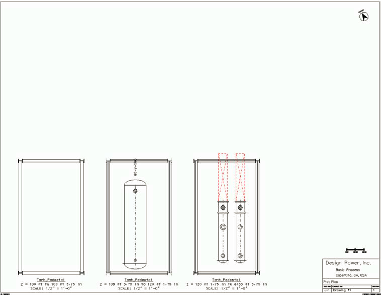
PlantDrafter detached plan
drawing.
- Fenced
Plan - If you want a drawing of a specific region of a model that
can be contained within a standard CAD fence – including view depth, then a
Fenced Plan is used.
While a region can be defined with a fence
drawn in any CAD view, a Fenced Plan drawing will always be in plan view.

A
fenced region of a model (upper left) selected for a PlantDrafter
drawing.
When a
PlantDrafter drawing is closed, the
model view is returned to its drawing seed state. This means that any clipping
of views you use to bound a region of the model is lost once a drawing is
closed. Because you may want to make template changes to a Fenced Plan drawing
without redefining the contents of the fence,
PlantDrafter will remember the
bounding coordinates of the fence most recently used for a Fenced Plan drawing.
These coordinates will stay in memory for as long as the model is open.
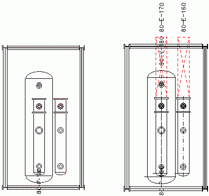
To generate a new Fenced Plan drawing based on
the previously drawn fence, you need only Open the drawing without drawing a
new fence. You are prompted with the message shown, to which the reply is
Yes.
No will cancel the Open drawing
command.
- Isometric -
PlantDrafter isometric drawings are
not intended to be used for pipeline isometric output. Rather, this drawing
view is intended to provide on overall view of a model.
Isometric drawings, similar to the one shown
below, cannot generate any of the annotations – pipeline centerlines, pipeline
tags, equipment centerlines – that are part of other
PlantDrafter drawings.
While equipment tags are never drawn, pipeline
graphics can be included in an isometric drawing by turning on their drawing
layers in the
Drawing Levels tab of the
PlantDrafter Template Editor.
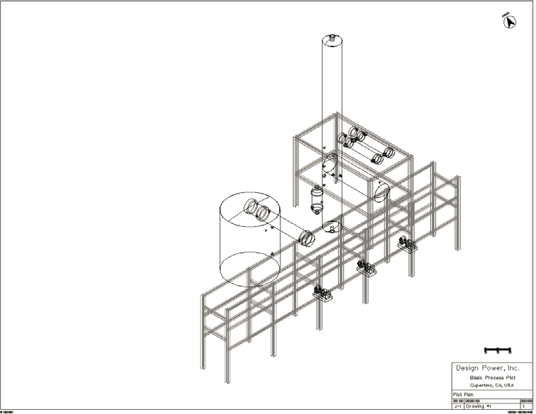
PlantDrafter isometric
drawing
|